Installing VOLO Controllers
This article describes how to install a VOLO Controller.
Wiring Instructions
Please review the wiring diagrams, here:
- VOLO Master Controller Wiring Diagram
- VOLO Expansion Controller Wiring Diagram
- VOLO Modem Wiring Diagram
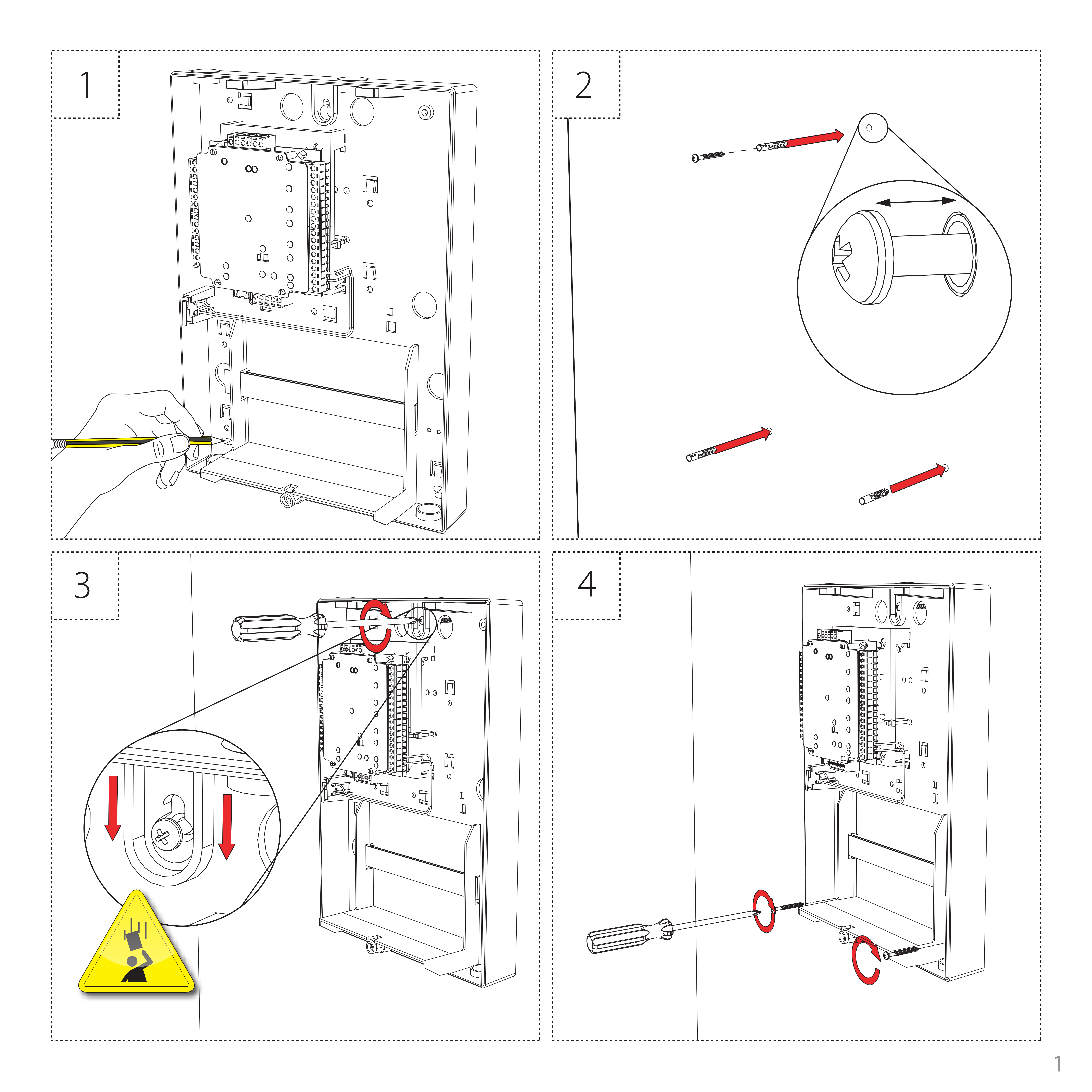
Mounting
The VOLO controller cabinet should be fixed to the surface with suitable fasteners; screws and wall plugs are provided for this in the fitting kit. Also provided are cable ties to secure the cabling and a smaller securing screw for the lid.
LED Diagnostics
| LED | Colour | Notes |
|---|---|---|
| Contact 1 | Orange | Door 1 contact closed |
| Contact 2 | Orange | Door 2 contact closed |
| RS-485 OUT | Orange | Unit receiving data |
| OK | Green | Flashing steadily on and off to indicate trying to connect |
| OK | Green | Blinking to indicate unit is connected (one brief flash per second) |
| OK | Green | On for 3 seconds then flashing, see diagnostics below |
| OK | Green | Flashing very quickly (only when performing a factory reset or updating firmware) |
| Server Connected | Orange | The TCP/IP interface is connected |
| Server Link | Green/Orange | 10/100 Mbits/sec |
| IN-1 to IN-4 | Orange | Activity on inputs IN-1 to IN-4 |
Overview
The Volo Master controller connects to the cloud-based server through a TCP/IP Ethernet port or through the supplied modem. If you are running a DHCP server on your network, then you do not need to configure the communication settings as a static IP address is not required. The article Configuring VOLO Controllers Using the Installer Tool explains how to configure the unit if you do not have a DHCP server. The supplied modem does not require any user configuration.
To add additional doors to the site, up to a maximum of 50, you will need to purchase one or more VOLO Expansion controllers. These connect via the self-terminating RS485 bus connection, no additional termination is required. Larger sites are accommodated by using multiple master units that can be logically grouped in the software.
caution
Please be aware that if you don’t have an Ethernet connection, the unit will attempt to connect through the mobile network, using the VOLO modem. This would require the purchase of a VOLO SIM licence.
Specifications
Electrical
| Electrical | Min | Max | Notes |
|---|---|---|---|
| Voltage | 11V DC | 24V DC (+20%) | |
| PCB Current (depending on activity) | 200mA | ||
| Relay switchable voltage | 24V DC (+20%) | ||
| Relay switchable current | 4A | ||
| General purpose outputs OUT-1, OUT-2 | 0.25A | @12V DC | |
| Combined reader port output current | 500mA |
Environmental
| Environment | Min | Max | Notes |
|---|---|---|---|
| Operating Temperature | 0°C | +55°C | |
| Waterproof | 200mA |
Communication
| Communication | Min | Max | Notes |
|---|---|---|---|
| Ethernet network speed | 10 Mbits/sec | 100 Mbits/sec | |
| Ethernet bandwidth requirement | 200 kbits/sec | ||
| DHCP Support | Yes | ||
| RS-485 network speed | 115.2 kbits/sec |
Features
| Features | Min | Max | Notes |
|---|---|---|---|
| Number of Cards | 0 | 100,000 | |
| Number of PINs | 0 | 100,000 | |
| Access Levels | 0 | 512 | |
| Timezones | 0 | 128 | |
| Door Open Time | 1 second | 99,999 seconds | |
| Data lines per system | unlimited | ||
| Doors per ACU | 2 | ||
| Reader ports per ACU | 2 | ||
| Readers per port | 2 | ||
| Keypads per port | 2 | ||
| ACU per data line | 25 (50 doors) | ||
| Data retention after total power loss | 7 days | ||
| Events stored in ACU with no server connection | 200,000 | ||
Product Dimensions
| Dimensions | Width | Height | Depth |
|---|---|---|---|
| Control Unit | 102 mm | 119 mm | 25 mm |
| Cabinet | 236 mm | 320 mm | 80 mm |